|
|
 |
|
Stepper Motors |
|
|
|
|
|
 Data Group: 1672 Data Group: 1672
SKU: 1141043
Weight (Kg): 0.5000
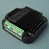
Decsription: UIM24204-SP
HS Code: 8483.40.9000
Applications:
 |
|
|
|
|
|
无标题文档
| UIM24204 |
STEPPER DRIVE,1,1/2,1/4,1/16 STEP,1.5-4A,12-40VDC,CAN SERIES |
42.3x 42.3x13.5mm,0.1KG,MOTOR 42/57/85/110 SERIES
|
| UIM24204-M |
STEPPER DRIVE,1,1/2,1/4,1/16 STEP,1.5-4A,12-40VDC,CAN SERIES |
42.3x 42.3x13.5mm,0.1KG,MOTOR 42/57/85/110 SERIES,ADVANCED MOTION CONTROL
|
| UIM24204-S |
STEPPER DRIVE,1,1/2,1/4,1/16 STEP,1.5-4A,12-40VDC,CAN SERIES |
42.3x 42.3x13.5mm,0.1KG,MOTOR 42/57/85/110 SERIES,2-P SENSOR INPUT
|
| UIM24204-SP |
STEPPER DRIVE,1,1/2,1/4,1/16 STEP,1.5-4A,12-40VDC,CAN SERIES |
42.3x 42.3x13.5mm,0.1KG,MOTOR 42/57/85/110 SERIES,3-P SENSOR INPUT
|
| UIM24204-M-S |
STEPPER DRIVE,1,1/2,1/4,1/16 STEP,1.5-4A,12-40VDC,CAN SERIES |
42.3x 42.3x13.5mm,0.1KG,MOTOR 42/57/85/110 SERIES,ADVANCED MOTION CONTROL&2-P SENSOR INPUT
|
| UIM24204-M-SP |
STEPPER DRIVE,1,1/2,1/4,1/16 STEP,1.5-4A,12-40VDC,CAN SERIES |
42.3x 42.3x13.5mm,0.1KG,MOTOR 42/57/85/110 SERIES,ADVANCED MOTION CONTROL&3-P SENSOR INPUT
|
| UIM24208 |
STEPPER DRIVE,1,1/2,1/4,1/16 STEP,3-8A,12-40VDC,CAN SERIES |
42.3x 42.3x13.5mm,0.1KG,MOTOR 42/57/85/110 SERIES
|
| UIM24208-M |
STEPPER DRIVE,1,1/2,1/4,1/16 STEP,3-8A,12-40VDC,CAN SERIES |
42.3x 42.3x13.5mm,0.1KG,MOTOR 42/57/85/110 SERIES,ADVANCED MOTION CONTROL
|
| UIM24208-S |
STEPPER DRIVE,1,1/2,1/4,1/16 STEP,3-8A,12-40VDC,CAN SERIES |
42.3x 42.3x13.5mm,0.1KG,MOTOR 42/57/85/110 SERIES,2-P SENSOR INPUT
|
| UIM24208-SP |
STEPPER DRIVE,1,1/2,1/4,1/16 STEP,3-8A,12-40VDC,CAN SERIES |
42.3x 42.3x13.5mm,0.1KG,MOTOR 42/57/85/110 SERIES,3-P SENSOR INPUT
|
| UIM24208-M-S |
STEPPER DRIVE,1,1/2,1/4,1/16 STEP,3-8A,12-40VDC,CAN SERIES |
42.3x 42.3x13.5mm,0.1KG,MOTOR 42/57/85/110 SERIES,ADVANCED MOTION CONTROL&2-P SENSOR INPUT
|
| UIM24208-M-SP |
STEPPER DRIVE,1,1/2,1/4,1/16 STEP,3-8A,12-40VDC,CAN SERIES |
42.3x 42.3x13.5mm,0.1KG,MOTOR 42/57/85/110 SERIES,ADVANCED MOTION CONTROL&3-P SENSOR INPUT
|
|
|
|
</td>
<td></td>
</tr>
<tr>
<td></td>
<td><table width="100%" border="0" cellspacing="1" cellpadding="1">
<tr>
<td width="2%"></td>
<td width="98%" colspan="2"><img src="/PDF/1672-1.jpg " alt=""><img src="/images/1672-1.jpg " alt=""></td>
</tr>
<tr>
<td width="2%"></td>
<td width="98%" colspan="2"><img src="/PDF/1672-2.jpg " alt=""><img src="/images/1672-2.jpg " alt=""></td>
</tr>
<tr>
<td width="2%"></td>
<td width="98%" colspan="2"><img src="/PDF/1672-3.jpg " alt=""><img src="/images/1672-3.jpg " alt=""></td>
</tr>
<tr>
<td width="2%"></td>
<td width="98%" colspan="2"><img src="/PDF/UIM24302_B.jpg" alt=""><img src="/images/UIM24302_B.jpg" alt=""></td>
</tr>
</table></td>
<td></td>
</tr>
<tr>
<td></td>
<td></td>
<td></td>
</tr>
<tr>
<td></td>
<td><hr align="center" width="100%" size="1" class="xian"></td>
<td></td>
</tr>
<tr>
<td></td>
<td><span class="style2"><span class="style5">©2003 KYSAN ELECTRONICS All Rights Reserved!<a href="http://www.kysanelectronics.com" target="_blank"> www.kysanelectronics.com</a></span></span></td>
<td></td>
</tr>
</table></td>
<td></td>
</tr>
<tr>
<td></td>
<td></td>
<td></td>
</tr>
</table>
</body>
</html>
| |